Tulip Prototyping
Initial Hardware Platform
The initial build for the tulip prototype will be extremely light. The follow is the initial schematic:
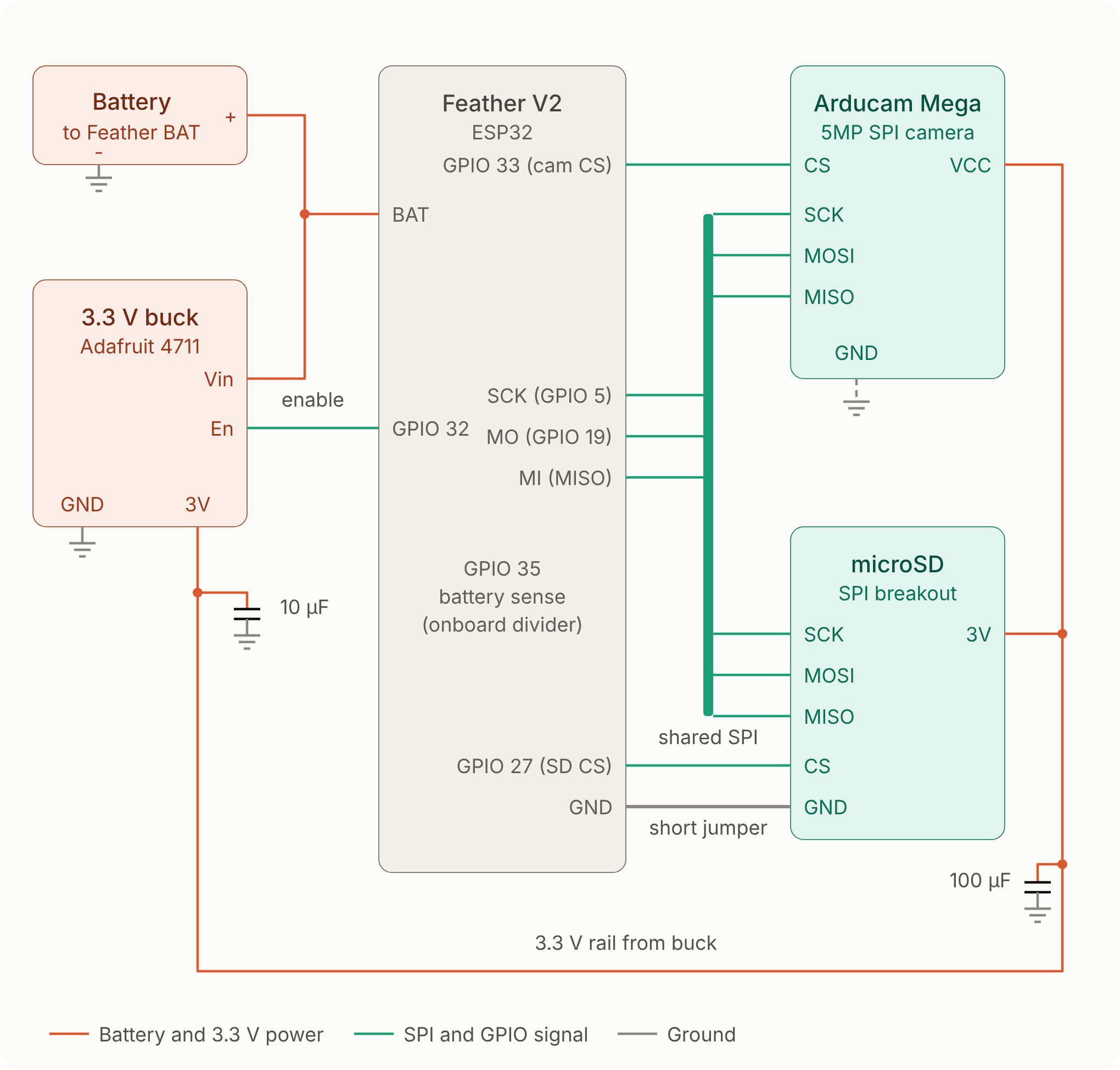
The initial implementation is based on the following components:
| Component | Purpose |
|---|---|
| Adafruit Feather ESP32 V2 | Primary microcontroller |
| Arducam Mega 5MP Autofocus (B040101) | Image capture |
| Adafruit TLV62569 3.3V Buck (#4711) | Regulated microSD power |
| Adafruit microSD Breakout (#4682) | Removable image storage |
| 6600 mAh Li-ion battery | Portable power source |
| 256 GB microSD card | Local photograph storage |
The architecture is intended to allow the ESP32 to remain in a low-power state between captures while the camera and storage peripherals are physically powered down.
Hardware compatibility, power behavior, and performance must be experimentally verified rather than assumed.
Assembly
I ordered most of the parts off of Adafruit.
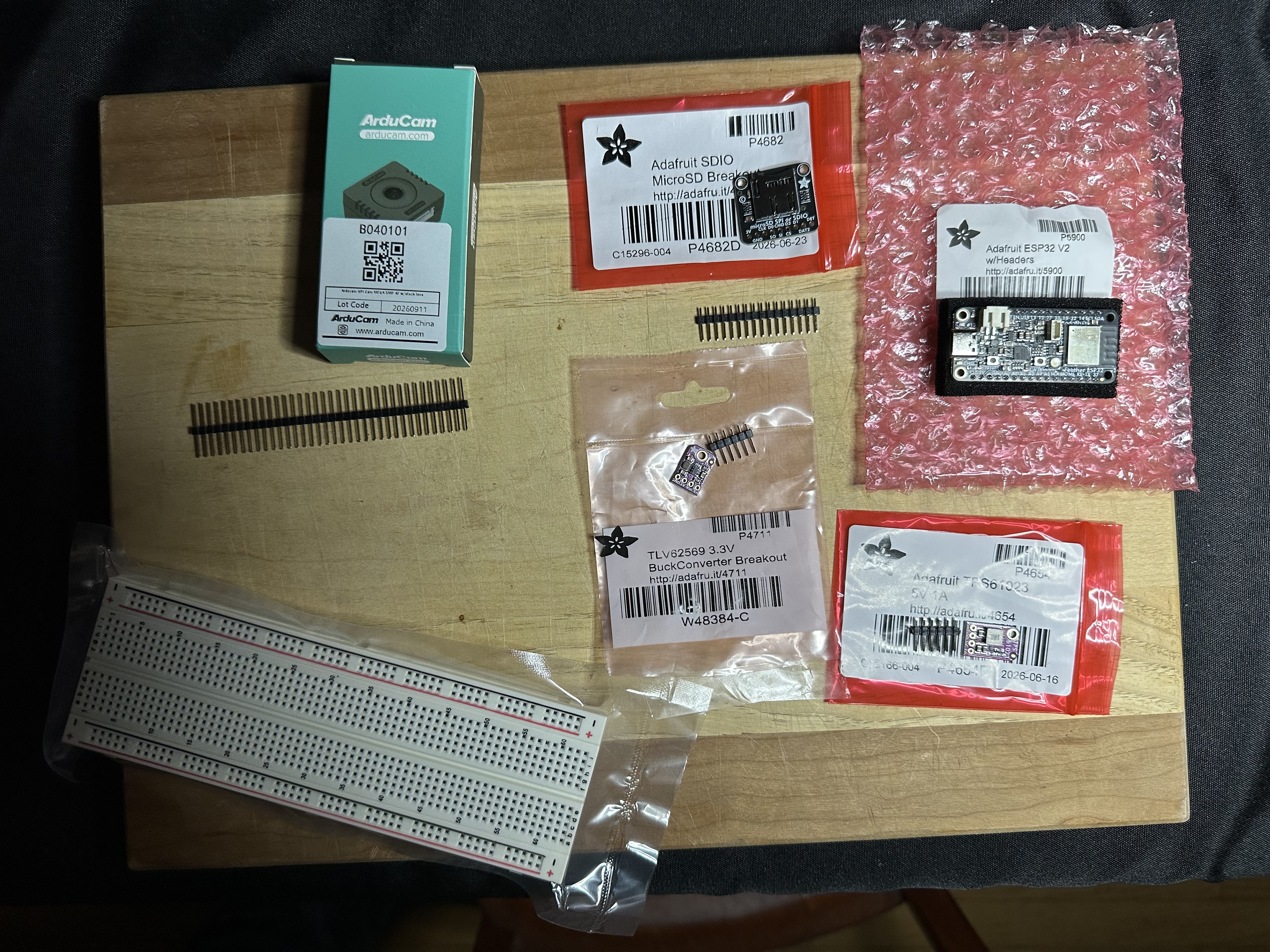
I’ve never soldered before, so it was time to learn. After a few practice runs, I soldered the header pins onto the buck and a MiniBoost that I didn’t end up needing.
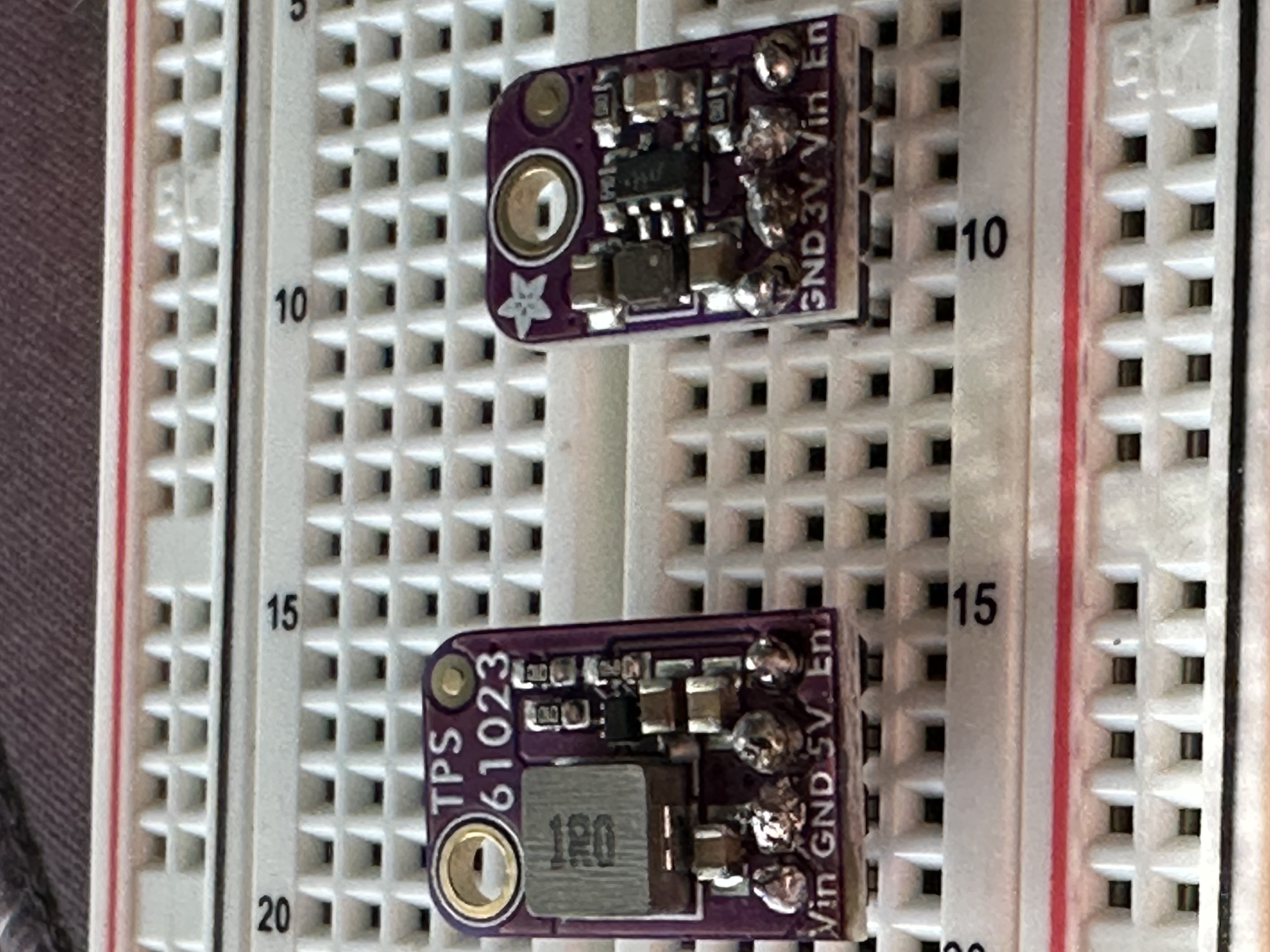
They came out much worse than my practice attempts. I had a lot of trouble getting the solder to not bead up and to stick. I eventually used extra flux. After some research, I wasn’t tining the solder iron enough in my practice and the tip had oxidized. I used a multimeter to test each connection to make sure there wasn’t a short. Thankfully the chips were still usable.
Since I need to do more soldering, I had to order a new tip and a flux pen.
In the meantime, I connected the Feather and the ArduCam to my breadboard.
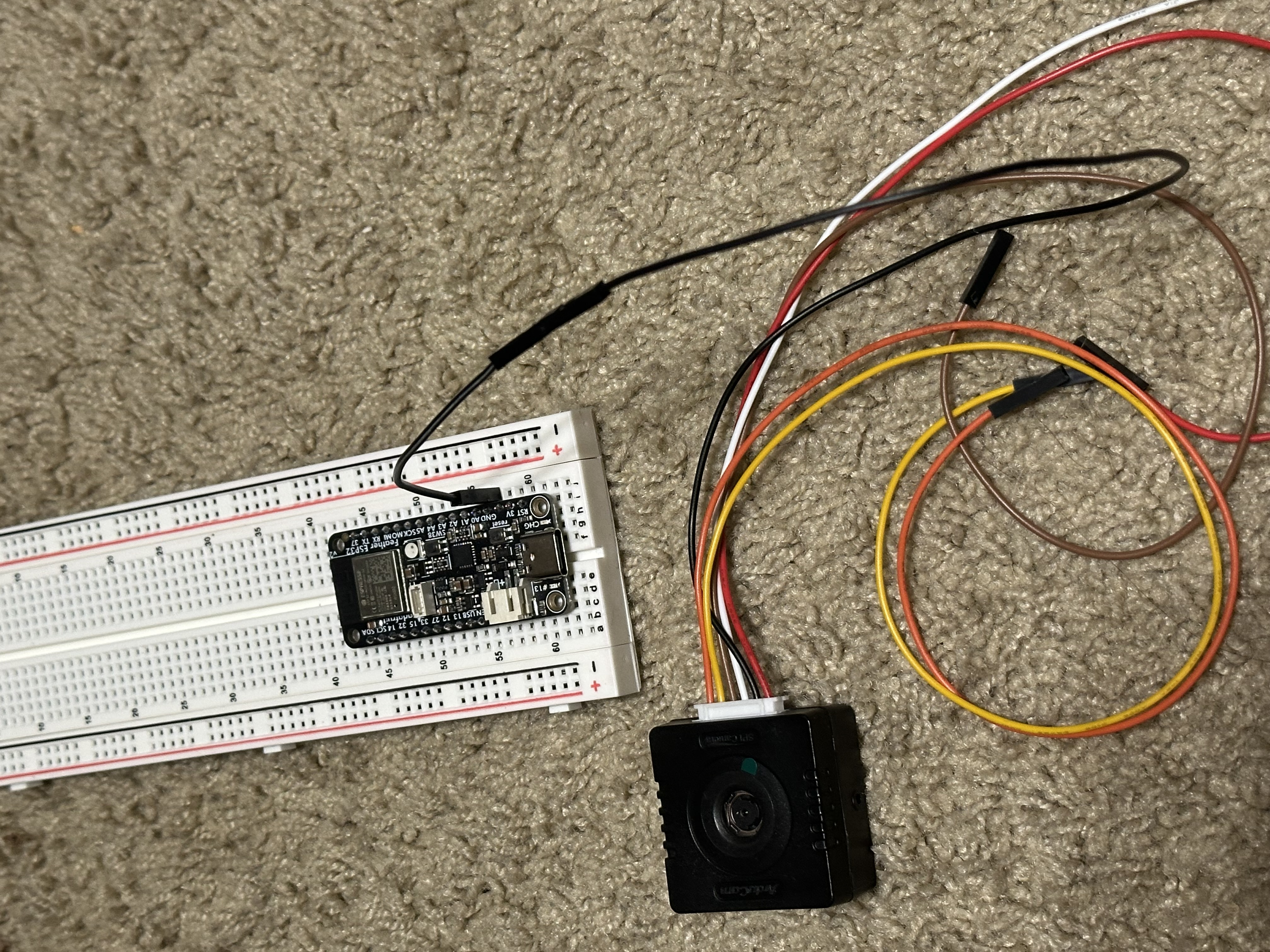
Using the serial connection with my MacBook, I verified the Feather powers up and was able to test the pins.
A few days later, my new soldering iron tip arrived and I soldered the header pins to the microSD breakout. These came out much better, although still not perfect. After the header pins were on, I added it to the breadboard along with the 3V buck.
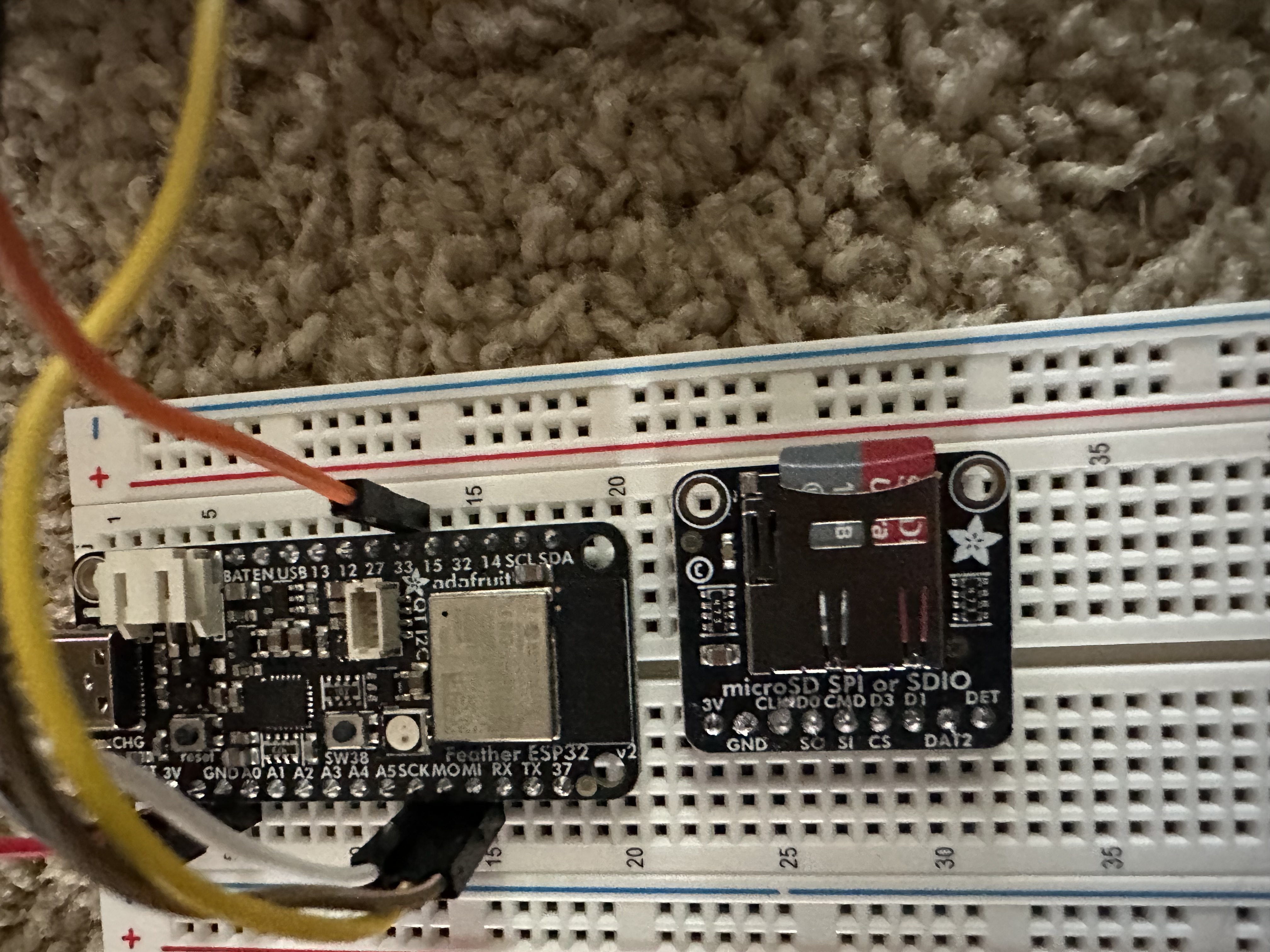
All the hardware was connected and ready for development of the software, except I found it very hard to consistently test the camera. Ideally I would have a full reproducable scene that I could use to test driving the different pins. My attempt to solve this was to steal some of my son’s Legos.
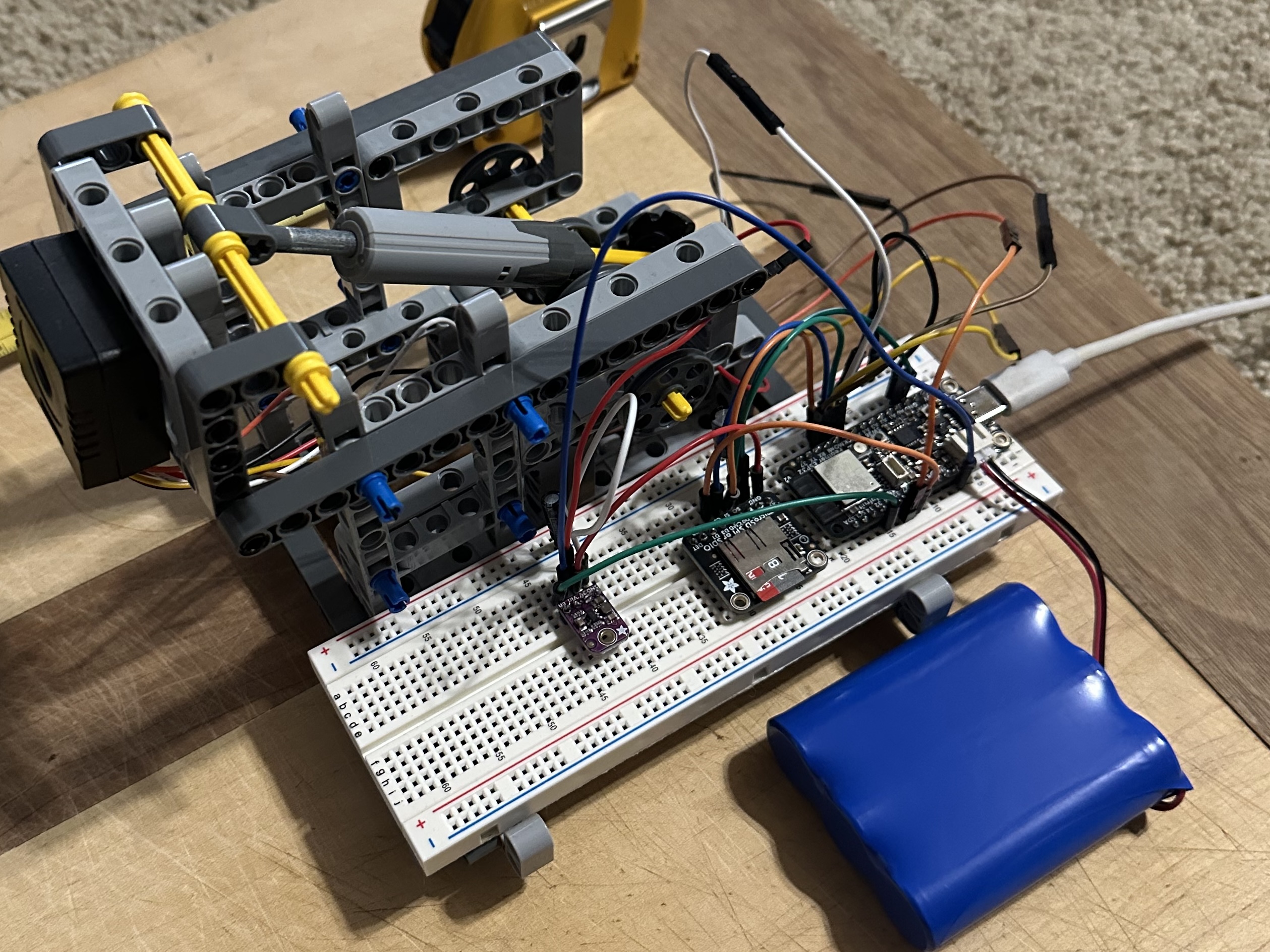
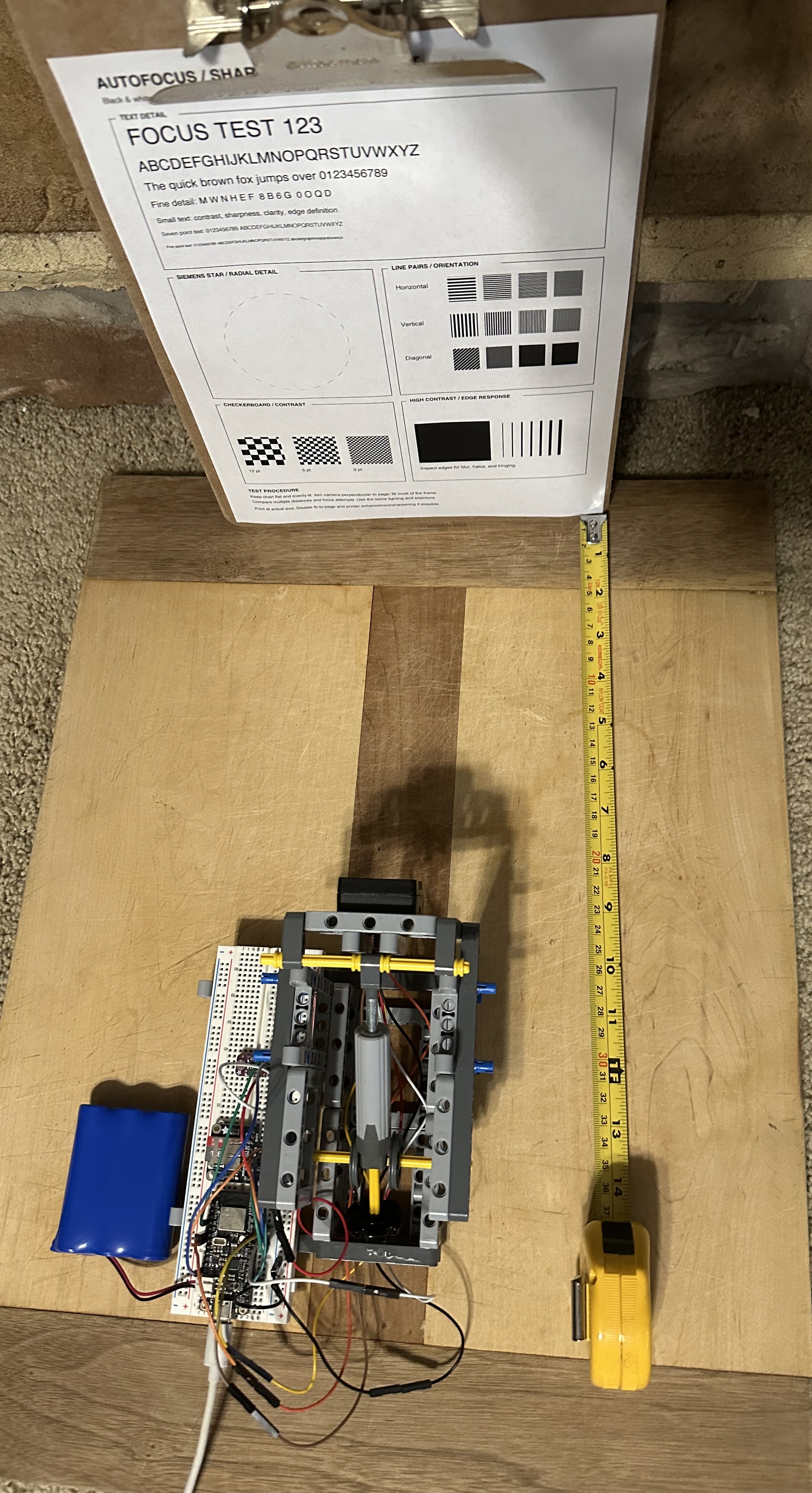
In addition to a stable frame, I added the ability to change the angle of the camera. With a focus test sheet and using different lighting schemes, I had a testable setup to continue with Stage A.